Hello, as an engineer from SuperPCBA, I am excited to present to you this article about circuit board soldering with utmost passion and professionalism. Soldering, as a crucial element in electronic manufacturing, directly influences the performance and stability of electronic products. In this article, we will delve into the definition, types, materials, techniques, and quality testing methods of soldering, aiming to provide you with a comprehensive overview of soldering technology and enhance your understanding of the essence of electronic product manufacturing.
Soldering is a critical step in connecting electronic components in electronic manufacturing, serving as the cornerstone not only for establishing connections but also for ensuring product performance and lifespan. SuperPCBA is committed to continually improving soldering technology, ensuring that our customers receive not just electronic products but also reliable quality through innovation and rigorous quality control.
Definition
Soldering in PCBs refers to the process of securely connecting electronic components to the Printed Circuit Board (PCB). This process aims to establish both electrical and mechanical connections, forming a complete circuit that enables the normal operation of electronic devices. Soldering is a crucial step in electronic manufacturing, ensuring the stability, reliability, and performance of circuits.
Specifically, soldering involves connecting the pins or connectors of components to the solder pads or through-holes on the PCB. This typically entails the use of solder materials such as solder and flux, employing heat processes like soldering irons, reflow ovens, wave soldering machines, or other appropriate methods to melt and flow the solder, ultimately creating robust soldered connections.
Soldering occurs at various stages of PCB manufacturing and includes Surface Mount Technology (SMT) soldering, Through-Hole Technology (THT) soldering, as well as manual soldering. Let’s delve into these different soldering methods and techniques.
Soldering Techniques
Surface Mount Technology (SMT):
SMT is a prevalent soldering technique involving the attachment of surface-mount components (such as chips, resistors, and capacitors) to a PCB using solder paste. The components are affixed to the PCB with the solder paste, and then heat, often from a reflow oven or infrared furnace, is applied to melt the solder paste and create a connection with the PCB pads. This method is suitable for small components and high-density circuit boards.
Through-Hole Technology (THT):

THT involves inserting the pins of through-hole components through holes in the PCB and soldering them on the opposite side. This process typically requires manual or semi-automatic soldering using a soldering iron or wave soldering technology.
Soldering Materials
Soldering involves the use of various materials, and the specific soldering materials vary based on the application, soldering type, and the specific characteristics required. Here are some common soldering materials, their characteristics, and operating methods:
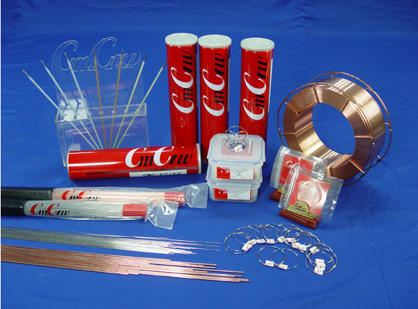
- Solder (Solder): Solder is a common soldering material used for connecting electronic components, typically an alloy of tin (Sn) and lead (Pb). Lead-free solder is also widely used for environmental considerations. Solder has a relatively low melting point, good fluidity, and is suitable for both Surface Mount Technology (SMT) and Through-Hole Technology (THT).
- Solder Paste (Solder Paste): Solder paste is a viscous mixture containing fine solder particles, flux, and solvent. It is primarily used in SMT, applied to PCB pads through printing or spraying, and forms solder joints during the reflow process.
- Solder Wire (Solder Wire): Solder wire is the wire-shaped form of solder, used for manual soldering or in some small-scale applications. Solder wire comes in different diameters and alloy compositions.
- Flux (Flux): Flux is a chemical substance used to remove oxides, improve the wetting of solder, and facilitate soldering. It can be part of the solder alloy or applied as a separate coating.
- Silver Epoxy (Silver Epoxy): Silver epoxy is a conductive adhesive commonly used to provide electrical connections between electronic components and PCBs. It offers good conductivity and mechanical strength.
When working with these soldering materials, operators need to choose the appropriate materials and follow the corresponding operating procedures based on specific soldering requirements and methods. This includes controlling soldering temperature, duration, and using the appropriate flux. Different soldering applications may require different soldering materials and processes.
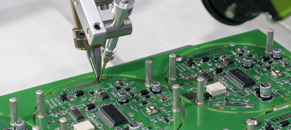
Soldering Techniques
Reflow Soldering:
- Working Principle: In reflow soldering, surface-mounted components on the printed circuit board (PCB) are attached to solder pads using solder paste. Subsequently, the entire PCB passes through a reflow oven or hot air oven, reaching the solder paste’s melting point to complete the soldering process.
- Features: Reflow soldering is the most common automated method in Surface Mount Technology (SMT), suitable for large-scale production. It facilitates the simultaneous processing of multiple components, enhancing production efficiency.
Wave Soldering:
- Working Principle: Wave soldering is applicable to PCBs with a mix of surface-mount and through-hole components. The PCB is passed over a solder wave, coated with molten solder, enabling the solder to adhere to the pads.
- Features: Wave soldering is typically used in Through-Hole Technology (THT) for plug-in components but can also be applied to certain SMT components.
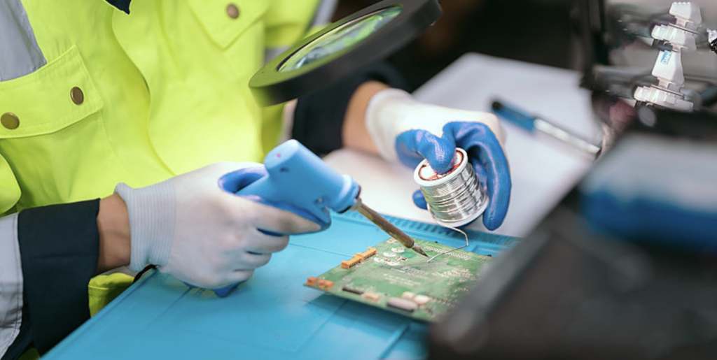
Manual Soldering:
- For specific scenarios, small-scale production, or prototype development, manual soldering may be necessary, involving the individual soldering of each component using a soldering iron.
Selective Wave Soldering:
- Selective wave soldering is a specialized form of wave soldering. It utilizes a mask to prevent the solder wave from contacting areas where soldering is not required, focusing only on the designated regions.
Various Welding Techniques Corresponding to Different Welding Technologies
Different welding preferences for various welding techniques
Wave soldering and reflow soldering, two types of automatic welding equipment, can be applied to some extent in both SMT and THT technologies. However, their application methods differ slightly in these two technologies.
Wave Soldering:
- SMT: In SMT, wave soldering is generally not the preferred method because the pins of SMT components are usually short and not suitable for soldering through a wave of solder. However, in some special cases, wave soldering can also be used for SMT components.
- THT: Wave soldering is more common in THT. For THT plug-in components, with longer pins, they are suitable for forming solder joints through wave soldering.
Reflow Soldering:
- SMT: Reflow soldering is a common soldering method in SMT. In SMT, the pins of components are short and can be affixed to the PCB using solder paste, forming solder joints through the reflow process.
- THT: While reflow soldering is not the primary method in THT, it can also be applied in some cases, especially when there are mixed SMT and THT components.
It’s important to note that, for SMT and THT technologies, reflow soldering is a more flexible and widely used automatic soldering method. It is suitable for various components, while wave soldering is more commonly used in specific scenarios. The choice of automatic soldering method often depends on production requirements, component types, and manufacturing processes. In large-scale production, especially in pure SMT processes, reflow soldering is the most common choice. Wave soldering may be more suitable for applications involving THT components or requiring higher mechanical strength.
Welding Quality Inspection
Quality defects that may occur during the welding process involve the physical and electrical properties of the solder joints. Below are some common welding defects and their corresponding detection methods:
Cold Solder Joint:
- Description: Cold solder joint refers to insufficient temperature during welding, resulting in incomplete wetting of solder on the pad or pin, forming an unstable connection.
- Detection Methods:
- Visual Inspection: Visually inspect the appearance of solder joints to check for uniform wetting.
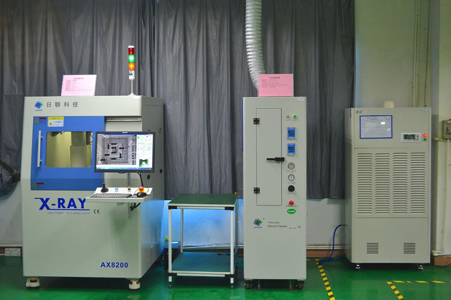
- X-ray Inspection: Used to examine solder joints hidden beneath components, especially for BGA (Ball Grid Array) and QFN (Quad Flat No-Leads).
- Microscopic Examination: Utilize a microscope to inspect solder joints, especially for small-sized components.
Through-Hole Insufficient Fill:
- Description: Through-hole solder joints are not completely filled, leading to an insecure connection.
- Detection Methods:
- X-ray Inspection: Examine the filling status of through-hole solder joints using X-ray.
- Cross-section Inspection: Cut through the cross-section of the solder joint to inspect the filling state of solder.
- Pull Strength Test: Test the strength of solder joints through a pull strength test.
Solder Cracks:
- Description: Cracks appear in the solder or soldering region, possibly caused by thermal stress or mechanical stress.
- Detection Methods:
- X-ray Inspection: Used to check for cracks in solder joints and the connection area.
- Ultrasonic Testing: Detect cracks inside solder joints using ultrasonic waves.
- Thermal Shear Test: Apply thermal stress to detect whether cracks occur in solder joints.
Short Circuit:
- Description: Undesirable short circuits form between solder points or adjacent circuits.
- Detection Methods:
- Electrical Testing: Use electrical testing instruments to detect abnormal electrical connections.
- Infrared Thermography: Detect hotspots on the circuit board, indicating potential short circuits.
- Microscopic Examination: Observe the physical connection of solder points and circuits.
Misalignment or Offset:
- Description: Components are not correctly aligned with solder pads or points, potentially leading to unstable connections.
- Detection Methods:
- Visual Inspection: Visually inspect the alignment of components and solder pads.
- Automated Optical Inspection (AOI): Use AOI systems to automatically inspect the position and alignment of components.
- 3D Imaging Technology: Employ three-dimensional imaging technology to detect the position and orientation of components.
These detection methods are often used in combination to ensure welding quality and reliability. In automated production, advanced technologies like AOI and X-ray inspection are widely applied, while visual inspection and manual testing tools may be more common in manual or small-batch production.
Conclusion
In concluding this article, we sincerely hope that our insights into circuit board soldering have provided you with profound and valuable knowledge. As a pivotal aspect of electronic manufacturing, the quality and technological prowess of soldering directly impact the performance and reliability of products. Leveraging our exceptional technical capabilities and extensive experience, SuperPCBA has been dedicated to delivering top-tier electronic manufacturing solutions to our clients.
Should you have any inquiries or collaboration needs related to soldering technology or other relevant fields, we extend a heartfelt invitation for you to reach out to us at any time. The SuperPCBA team is committed to offering professional consultation services, tailoring optimal electronic manufacturing solutions to meet your specific needs. Let us collaborate to shape the future and infuse your electronic products with greater strength and vitality!