Printed Circuit Boards (PCBs) are widely used in various electronic devices, ranging from small and simple electric toys, household appliances, ubiquitous smartphones, and computers, to large and complex automated equipment in factories. All of these devices rely on quality-assured PCBs to function correctly. If a PCB has defects or manufacturing issues, it can exhibit various problems in different environments. These issues may include instability under different conditions, electrical connectivity problems, electromagnetic interference (EMI), electromagnetic compatibility (EMC) issues, data transmission errors, safety concerns, and more.
In such cases, manufacturers may have to recall these devices, resulting in significant losses for the manufacturer and eroding consumer trust in the product. Therefore, conducting appropriate tests on PCBs and control boards during the production process is a critical step in ensuring the quality and reliability of these circuit boards. These tests can help identify potential issues and address them before the product enters the market. This, in turn, reduces maintenance and recall costs, enhances customer satisfaction, and ensures the long-term reliability of the product.
The Necessity of PCB Testing

Conducting rigorous testing during the circuit board manufacturing process is an indispensable step. PCB testing is crucial for ensuring product quality, performance, reliability, and safety. It helps prevent issues, reduce costs, maintain reputation, and ensure successful market competitiveness. Here are several important reasons why PCB testing is considered highly necessary:
- Quality Assurance: PCB testing can detect and identify manufacturing defects such as soldering issues, shorts, open circuits, component flaws, and more. This helps ensure that the quality of the circuit board meets standards and prevents low-quality products from entering the market.
- Performance Verification: Through testing, it is possible to verify whether the circuit board meets design specifications and performance requirements. This ensures that the product operates as expected, providing consistent performance that meets customer demands.
- Reliability Assurance: PCB testing helps uncover potential reliability issues such as component lifespans, temperature concerns, and heat management. This contributes to extending the product’s lifespan and reducing maintenance and replacement costs.
- Safety Assurance: Circuit board testing can identify potential electrical and electromagnetic interference issues, as well as problems that could lead to data breaches or security vulnerabilities. This helps ensure the safety of the product and reduces potential risks.
- Regulatory Compliance: Many electronic products must comply with regulations and compliance requirements to ensure safety and environmental friendliness. Testing ensures that the product complies with these regulations, avoiding legal liabilities and market access issues.
- Reduced Maintenance Costs: PCB testing helps discover and address issues before products enter the market, reducing maintenance and recall costs. It prevents quality issues from triggering post-delivery repair demands.
- Customer Satisfaction: By delivering high-quality, reliable products, PCB testing can enhance customer satisfaction and increase customer loyalty. Products that haven’t undergone testing may lead to customer complaints and returns.
- Traceability: By recording and tracking test results, product traceability can be established. This is crucial for quickly identifying and resolving issues when they arise.
In summary, PCB testing is a critical step in ensuring product quality, performance, reliability, and safety. It offers numerous benefits, including quality assurance, regulatory compliance, reduced maintenance costs, and enhanced customer satisfaction, making it an essential part of the manufacturing process.
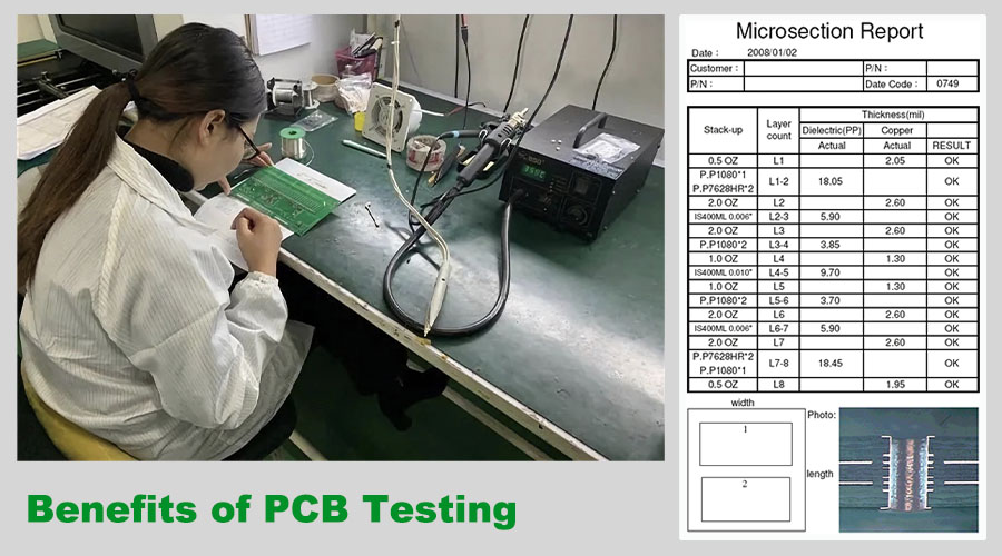
Benefits of PCB Testing
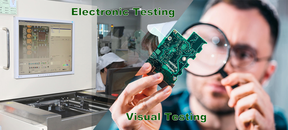
PCB testing comprises two major categories: “Electronic Testing” and “Physical Testing.” Both electronic and physical testing play indispensable roles in ensuring product performance, quality, and reliability. Together, they constitute vital quality control steps in the manufacturing process of circuit boards and control boards. Below, we will separately explain the distinct roles they play in ensuring the quality of circuit boards and control boards during production.
Electronic Testing Benefits:
“Electronic Testing” or “Electronic Device Testing” primarily focuses on assessing the performance and quality of electronic products like circuit boards and control boards. These tests can include using various instruments and equipment to measure parameters related to the electrical characteristics, connectivity, functionality, reliability, and more of the circuit board. Therefore, they can be categorized as part of “Instrumentation Testing” since they involve the use of various testing instruments and devices to perform these tests. These instruments may include digital oscilloscopes, multi-purpose testers, spectrum analyzers, power supplies, thermal cycling test equipment, and more. The following are the main components of electronic testing:
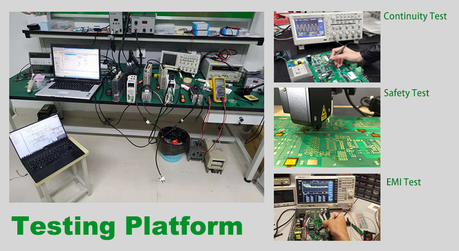
- Continuity Test: This is the most basic test used to detect continuity and open circuits within the circuit, ensuring that all circuit paths are correctly connected.
- Electrical Test: This includes testing the components on the circuit board (e.g., resistors, capacitors, diodes, transistors, etc.) to ensure they are functioning correctly. This also involves power consumption testing and power analysis.
- Functional Test: These tests cover the actual functions of the circuit board. They verify whether the circuit board operates normally according to design specifications, including various inputs and outputs.
- Timing Test: These tests are used to verify the timing relationships within the circuit to ensure data is transmitted at the correct times and in the correct sequence.
- Analog Test: Used to test the performance of analog circuits, such as amplifiers, filters, and sensors.
- Electromagnetic Interference Test (EMI): This test checks whether the circuit board generates electromagnetic interference or is susceptible to external electromagnetic interference. It is crucial for ensuring compliance with electromagnetic compatibility (EMC) requirements.
- Temperature Test: Performance testing of the circuit board at different temperatures to verify its reliability within a wide temperature range.
- Reliability Test: These tests simulate the performance of the circuit board over extended periods of use and under various environmental conditions to assess its lifespan and reliability.
- Safety Test: Ensures that the circuit board complies with relevant electrical and safety standards to prevent potential safety issues.
- Communication Test: Tests the communication interfaces of the circuit board to ensure the reliability of data transmission.
- Data Storage and Processing Test: These tests cover the storage and processing functions on the circuit board to ensure the ability to handle and store data.
Physical Testing Benefits:
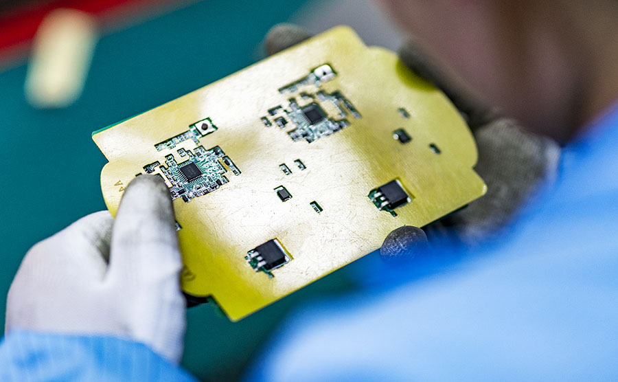
Physical testing or visual inspection is primarily used to ensure the correct installation of components and the quality of soldering. These aspects often require manual inspection but can also be aided by instruments like microscopes and infrared thermal imaging devices. The following are the main components of physical testing:
- Component Installation Quality: Visual inspection is used to assess the correct installation of components, positional accuracy, and stability. It ensures that components are not tilted, misaligned, or loose.
- Soldering Quality: Visual inspection and physical examination are used to inspect the quality of solder joints. It ensures that solder joints are uniform, complete, free from cold solder, dry solder, over-soldering, or solder flux residues.
- Pin and Pad Quality: Inspecting the pins of components and the corresponding pads they are connected to, ensuring they are not bent, damaged, or impaired, ensuring connection quality.
- Physical Damage: Visual inspection is used to identify physical damage on the circuit board, such as scratches, cracks, breakages, deformations, etc. This helps prevent issues during transportation or use.
- Appearance and Marking: Inspecting the appearance, labeling, tags, and printing on the circuit board to ensure they are clear, accurate, and durable, meeting quality standards.
- Component Integrity: Ensuring that all necessary components are correctly installed without missing or duplicate installations.
- Mechanical Stability: Physical examination is used to ensure that components are securely fastened to the circuit board to prevent loosening or vibration.
- Encapsulation and Casing Integrity: Inspecting the integrity of the casing or encapsulation to ensure there are no cracks, gaps, or sealing issues.
Electronic testing and physical testing are typically conducted at different stages of the manufacturing process, and the specific testing methods and scope may vary depending on the application and requirements of the circuit board. However, they both contribute to ensuring the quality and reliability of circuit boards and control boards. This helps reduce potential issues during the actual use of electronic products and is an essential step in the quality control process, ensuring that the manufacturing quality of electronic products meets standards and specifications.
commonly used PCB testing methods
PCB testing has become an indispensable part of the printed circuit board (PCB) manufacturing process. It helps in the timely detection of issues, assists personnel in quick resolution, and ensures high-quality PCBs. There are various methods for testing PCBs, and different approaches can be employed based on specific needs and testing objectives. These testing methods could be also divided into 2 types: Electronic Testing Methods and Physical Testing Methods:
Electronic Testing Methods:
- In-Circuit Testing (ICT): ICT, or In-Circuit Testing, is an essential testing method for modern PCB manufacturers. It is a powerful tool that involves using test probes to make contact with test points on the PCB layout. ICT is used to detect open circuits, short circuits, and faults in all components of a PCBA. It provides clear instructions to personnel. ICT has a wide range of applications, offers high measurement accuracy, and makes it easy for even moderately skilled workers to handle PCBAs with issues. Using ICT can significantly improve production efficiency and reduce manufacturing costs.
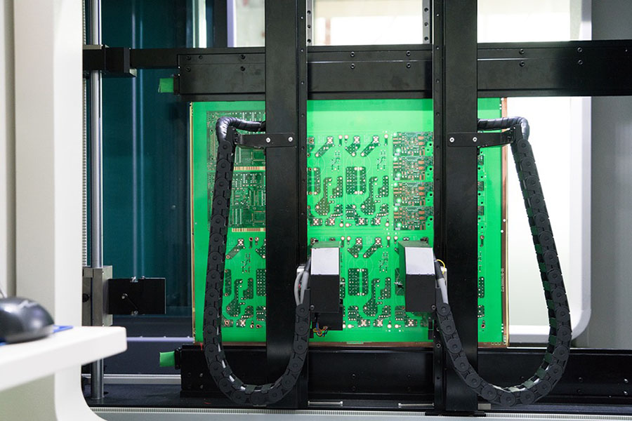
- Flying Probe Testing: Flying probe testing is a recognized and cost-effective method for improving circuit board standards. It is an alternative to traditional testing methods that involve fixed test probes. Instead, flying probe testing uses two or more independent probes that run without fixed test points. These probes are mechanically controlled and move according to specific software instructions. As a result, flying probe testing has lower initial costs since it can be accomplished through software modifications without altering fixed structures. While flying probe testing is more cost-effective for small batch orders, ICT is faster and less error-prone, making it more cost-effective for large batch orders.
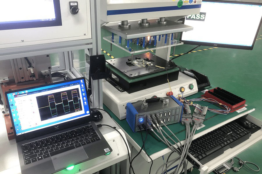
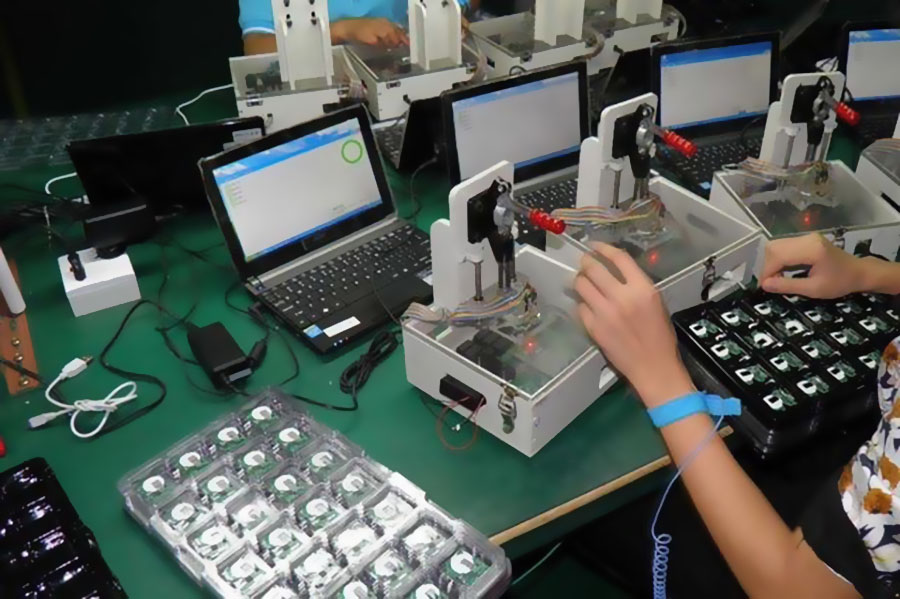
- Functional Testing: Functional system testing involves comprehensive testing of the functional modules of a circuit board at the middle and end of the production line to confirm the board’s quality. Functional testing includes two main types: Final Product Test and Hot Mock-up. Functional testing typically does not provide in-depth data (such as pin locations and component-level diagnostics) for process improvement and requires specialized equipment and custom test programs. Writing functional test programs is complex, making it less suitable for most PCB production lines.
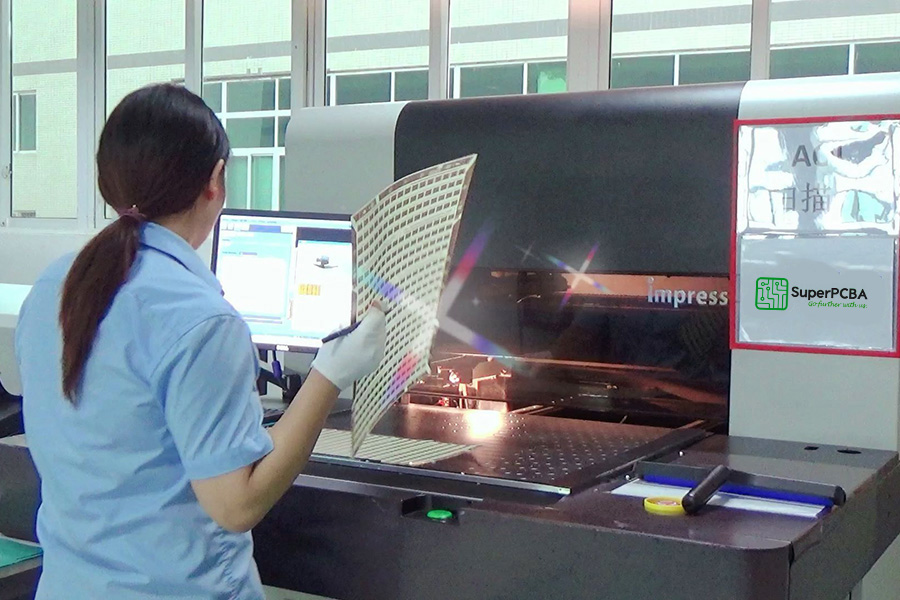
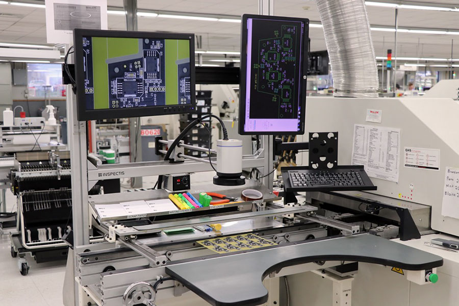
- Automated Optical Inspection (AOI): AOI uses one or two cameras, either 2D or 3D, to capture images of the PCB, which are then compared to detailed schematics. Any mismatches between the PCB and the schematics are marked for review by technicians. AOI detects faults promptly but does not power the PCB. It cannot detect all component issues, so it is often used in combination with other testing methods. Common test combinations include AOI with flying probe testing, AOI with ICT, and AOI with functional testing.
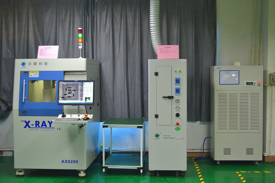
- X-ray Testing: X-ray testing, also known as X-ray inspection, uses low-energy X-rays to rapidly detect issues such as open circuits, short circuits, solder bridges, and solder voids on a PCB. X-ray testing is primarily used to inspect ultra-fine pitch and high-density defect PCBs, as well as defects produced during assembly, including bridging, missing chips, and misalignment. It can also use tomography to detect internal defects in IC chips, making it the only method to test the quality of ball grid arrays (BGAs) and solder ball bonding.
- Laser Testing: Laser testing is the latest development in PCB testing technology. It scans the PCB with a laser beam, collects measurement data, and compares the actual measurements to predefined acceptance limits. The technology has been validated on bare boards and is being considered for use in assembly board testing. It offers high speed, no fixtures are required, and it provides clear visual results. However, it comes with high initial costs, maintenance, and usage issues.
- Aging Testing: Aging testing simulates various factors that can cause products to age under real usage conditions. Its purpose is to assess the stability and reliability of products in specific environments. Products are placed under specific temperature and humidity conditions for extended periods, typically 72 hours to 7 days, while performance data is recorded. The results are used to improve the production process to ensure product performance meets market demands. Aging testing typically refers to electrical performance testing and may include other tests such as drop testing, vibration testing, and salt spray testing.
- Solderability Testing: Ensures surface integrity and increases the likelihood of forming reliable solder joints.
- PCB Contamination Testing: Detects ion contamination that can potentially corrode PCBs and lead to other issues.
- Microsection Analysis: Investigates defects, open circuits, short circuits, and other failures.
- Time Domain Reflectometer (TDR): Detects faults in high-frequency boards.
- Peel Strength Testing: Determines the strength required to delaminate a laminated board from the substrate.
- Float Testing: Identifies the level of thermal stress PCB holes can withstand.
Physical Testing Methods:
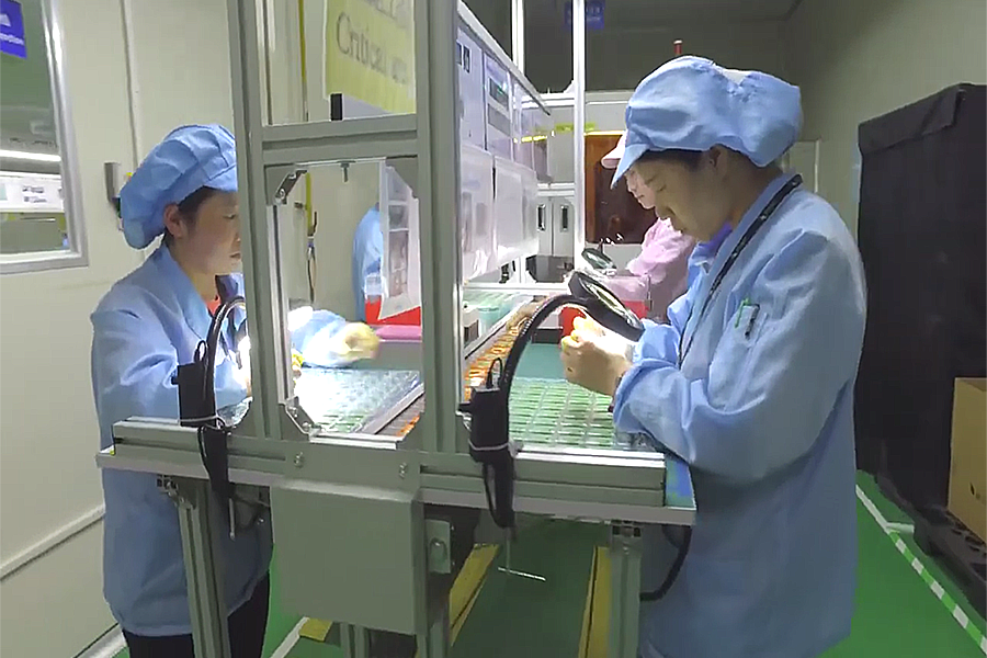
Visual testing of circuit boards is a method of detection that relies on manual visual examination of various aspects of the PCB, including components, connections, and solder joints. Here are some common methods of visual inspection for circuit boards:
- Magnifying Glass Inspection: This method involves using a magnifying glass to enlarge details on the circuit board, making it easier to observe components, pins, and solder pads.
- Microscope Inspection: Microscope inspection allows for high-magnification observation, enabling the examination of tiny details of components, such as pin quality and alignment.
- Lighting Measures: Appropriate lighting devices, such as LED lighting, infrared lighting, or ultraviolet lighting, are used to improve observation conditions.
- Comparison and Marking: By using reference samples or standard schematics, observed components are compared against established standards to ensure correctness and quality.
- Checklists and Documentation: Inspection results are meticulously recorded using checklists or documentation tools, including any identified issues, their locations, and their nature.
- Visual Examination of Appearance: The overall appearance of the circuit board is examined, including the enclosure, packaging, and labeling, to ensure there are no damages, blemishes, or foreign objects.
- Solder Joint Inspection: Solder joint quality is assessed, including solder pads, solder wires, and solder flux, to ensure there are no soldering issues such as cold soldering or voids.
- Component Installation Inspection: The components on the circuit board are checked to ensure they are correctly installed, without tilting, misalignment, or damage.
- Continuity Inspection: Wires, connectors, and harnesses on the circuit board are inspected to ensure secure connections, correct attachment, and the absence of open circuits or short circuits.
- Mechanical Stability Inspection: The mechanical stability of the circuit board is verified, ensuring that support structures and fixtures are secure and reliable.
These methods are typically performed by experienced inspectors who follow product specifications and design requirements. Visual inspection is an effective quality control method but can be subject to the subjective judgment and visual limitations of inspectors. Therefore, it is often combined with other automated testing methods to enhance detection accuracy and efficiency.
Make your PCB design withstand PCB testing and market scrutiny
Ensuring that your PCB design can withstand PCB testing and market scrutiny is crucial. Here are some methods and strategies:
- Strictly Follow Design Specifications: Before designing the PCB, make sure to thoroughly understand and adhere to relevant design specifications and standards. This includes electrical standards, electromagnetic compatibility (EMC) standards, safety standards, and more. Consider these standards during the design process to ensure compliance during testing and in the market.
- Prototype Testing: Before mass production, create one or more prototypes for testing and validation. This helps identify potential issues that can be addressed, reducing problems during the production phase.
- Simulation and Modeling: Use circuit simulation tools to simulate and validate circuit performance. This helps identify and rectify issues before actual manufacturing.
- Rigorous PCB Layout and Routing: The layout and routing of the PCB are critical for performance and EMC. Ensure signal integrity and prevent electrical interference and crosstalk.
- Appropriate Component Selection: Choose high-quality, reliable components and ensure they meet specifications. Low-quality components can lead to problems during testing and actual use.
- Heat Management: Implement effective heat management measures, especially for high-power circuits, to ensure the PCB doesn’t overheat during prolonged operation.
- Design for Testability: Consider testing requirements during PCB design. Ensure easy access to test points and include test interfaces in the design to expedite the testing process.
- Testing Plans and Procedures: Develop comprehensive testing plans and procedures to ensure thorough testing of all functions and performance aspects. This includes functional testing, electrical testing, EMC testing, and more.
- Continuous Improvement: Take appropriate measures to improve the design based on issues discovered during testing and in the market. This may involve design modifications, component changes, or process improvements.
- Collaborate with Testing Labs: If possible, collaborate with professional testing laboratories for validation and certification. They can provide specialized testing equipment and technical support.
- Market Feedback: Monitor market feedback and customer input to understand product performance and issues in real-world use. Make improvements based on this feedback.
- Training and Certification: If you or your team lacks sufficient testing and certification experience, consider training or hiring certified engineers with expertise in this area.
In conclusion, ensuring that a PCB design can withstand testing and market scrutiny involves considering multiple factors, including design, testing, quality control, and market feedback. Taking appropriate measures and strategies can enhance product quality and reliability while reducing the risks of testing and market issues.
CHOOSE SuperPCBA FOR PCB Manufacturing and Testing
PCB testing is an indispensable part of the printed circuit board manufacturing process. It helps detect issues promptly, assists personnel in quick resolution, ensures high-quality PCBs, and prevents quality problems that could damage a brand’s reputation when products hit the market. Choosing the right supplier not only ensures smooth testing of your products but also guarantees the quality of PCBs and control boards from the source of design and production. With years of production management experience, top-notch testing equipment, and strict testing processes, SuperPCBA is committed to providing customers with highly reliable and high-quality circuit boards. Feel free to inquire for more information.